Easy Collaboration with Terraform Cloud

Our team at Rubrik uses Terraform extensively to manage our infrastructure as code. This means that our infrastructure configurations are version controlled and resources are provisioned in an automated fashion through CI/CD workflows. Because it’s a customer-zero environment, we’re constantly evaluating new tools to find better ways to manage and scale the environment. This led us to trying out Terraform Cloud. 

Easy collaboration is the name of the game with Terraform Cloud. It offers team-oriented remote execution and is consumed as a SaaS platform. In this post, I’ll cover remote state management, cost estimation, and collaboration with Terraform Cloud.

Remote State Management

State files capture the existing state of provisioned infrastructure for a specific workspace. State files are stored on the local machine by default. This becomes unwieldy when the rest of the team is involved. 

Remote state management is a design consideration with which we’ve extensively experimented. My colleague, Chris Wahl, has written about using Amazon S3 to store state, which is how we have historically managed state. This resembles the following:

terraform {
  backend "s3" {
    bucket = "technicloud-bucket-tfstate"
    key    = "dev/terraform.tfstate"
    region = "us-east-1"
  }
}

Using Terraform Cloud to manage remote state resembles the following:

terraform {
  backend "remote" {
    hostname     = "app.terraform.io"
    organization = "technicloud"

    workspaces {
      name = "scaling-compute"
    }
  }
}

With Terraform Cloud, the state file is abstracted from the user; it exists but is secured and managed by the platform. This allows for granular access control, versioning, and backup so that I’m able review previous points in time. While Amazon S3 provides these same features, it requires quite a bit more effort to do so. For example, remote state management with Terraform Cloud provides integrated locking, eliminating the need to spin up a DynamoDB table.

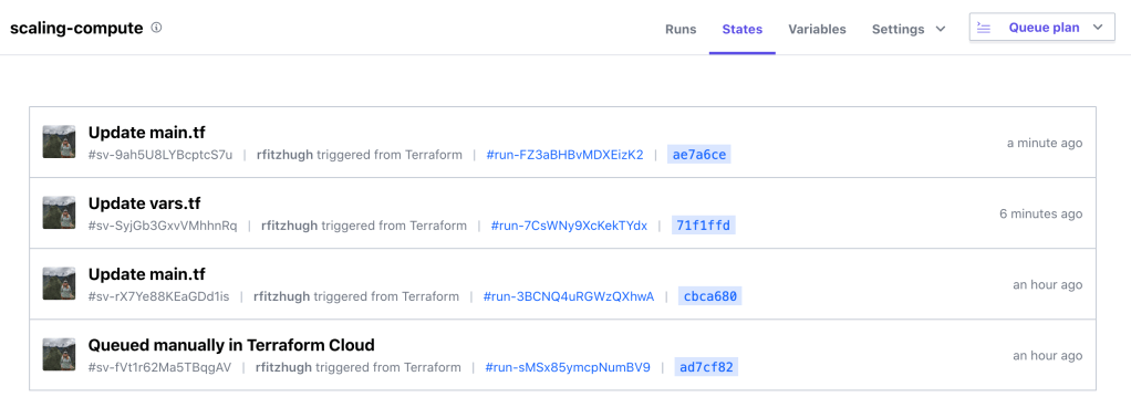
Terraform Cloud enables teams to easily collaborate asynchronously by using the platform as remote state file storage.
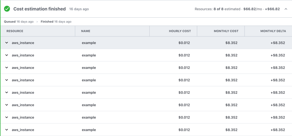
Cost Estimation

A very cool feature that stood out was the cost estimation, which displayed an approximate monthly cost with each workflow run. This is particularly beneficial to me because we use Terraform to deploy resources across all three major cloud service providers. Holistic billing management across multiple clouds has long plagued me:

https://platform.twitter.com/widgets.js

This standard interface provides a valuable way for our team to analyze, report on, and visualize cloud spend across cloud providers.

While this alone does not give a complete picture of our monthly bill, it certainly helps us be mindful of cost when testing and building demos. We are regularly building demos to showcase our product’s cloud functionality; this process consists of design time spent architecting a solution and then usually a lot of prototyping to get the demo perfect. The prototyping phase consists of deploying and destroying resources numerous times, which can quickly rack up a big bill when not paying attention to cost.

However, the Terraform Cloud Cost Estimation API provides a lot of granular data that can be pulled into our central billing dashboard. This helps us be mindful of monthly costs to operate our cloud environment. Using this data, we made the decision to use demo leases of 4 hours to help minimize costs for demo; after 4 hours, the resources are stopped. This helps us keep central IT off our backs 🙂

Team Collaboration

Terraform Cloud offers a number of collaboration features to help teams easily work together. Our team prioritizes making our code as reusable as possible; we regularly write modules that fit our design specifications and use cases. The Private Module Registry allows us to easily share the different use case modules that we’ve built. 

There’s also multi-tenancy with the ability to create and manage multiple teams and organizations and enforcing Role Based Access Control (RBAC) across the different workspaces. Moreover, you can manage Terraform Cloud configurations using Terraform.

Here’s an example of using the Terraform Cloud provider to create an organization, workspace, team, and permissions:

# Create the Terraform Cloud Organization
resource "tfe_organization" "technicloud" {
 name  = "technicloud"
 email = "rebecca@technicloud.com"
}
 
# Create the Technicloud Workspace
resource "tfe_workspace" "technicloud-wordpress" {
 name         = "technicloud-wordpress"
 organization = tfe_organization.technicloud.id
}
 
# Add Web Dev Team
resource "tfe_team" "web-dev" {
 name = "technicloud-web-dev"
 organization = tfe_organization.technicloud.id
}
 
# Add User to Web Dev Team
resource "tfe_team_member" "user1" {
 team_id  = tfe_team.web-dev.id
 username = "rfitzhugh"
}
 
resource "tfe_team_access" "test" {
 access       = "plan"
 team_id      = tfe_team.web-dev.id
 workspace_id = tfe_workspace.technicloud-wordpress.id
}

So basically…

You can find the above code sample on GitHub.

Summary

In this post I reviewed a handful of compelling Terraform Cloud features. This includes remote state management, cost estimation, and collaboration features. Consider using Terraform Cloud for state storage and collaboration (especially the Private Module Registry), it’s free for small teams (up to 5)! Since we do not yet use Sentinel, I did not get a chance to test out Sentinel policies with Terraform Cloud but hope to implement it soon. 

If you have any questions, please reach out to me on Twitter.

Hello, Terraform

At work, my team owns and maintains a large lab environment for the development and testing of Rubrik Build projects. It was built in a hurry, causing some of our original design principles to be compromised. My team and I have decided to use this no-travel period as an opportunity to redesign and redeploy our lab environment. I will review our design in a later post. 

One of our design goals is to leverage infrastructure as code principles (where possible). The team’s primary tool of choice for provisioning is Terraform

Terraform allows us to define what resources we need in a declarative manner, where we simply define the end state needed for our infrastructure. Here’s a few reasons why we like using Terraform:

  • Multi-platform, similar operations across a number of providers
  • Easy provisioning and deprovisioning of resources
  • Idempotent, saves current state as a file
  • Detects diffs from current state when applying changes

This post will dive into Terraform syntax, architecture, and operations.

Terraform Syntax

The low-level syntax of Terraform is defined in HashiCorp Configuration Language (HCL). The following example shows a generic configuration code block for Terraform:

command_type "provider_resource_label" "resource_label" {
  argument_name = "argument_value"
  argument_name = "argument_value"
}

Let’s dig into the syntax:

  • Command — the command type resource tells Terraform you want to create a resource, such as an S3 bucket or an EC2 instance.
  • Provider Resource Label — this is the type of resource you want to create. The resource name is specified by the provider. For example, you may use aws_instance to provision an EC2 instance using the AWS provider.
  • Resource Label — this what you want to colloquially label the resource within your Terraform configuration. This label should be unique within this configuration file as it is used later when referencing the resource.
  • Arguments — allows you to specify configuration details for the resource being provisioned. These are defined as an argument name and an argument value. As an example, when provisioning an EC2 instance, you may want to specify which AMI is used. 

Note that comments using # or // or even /* or */ are supported. 

To put these concepts together, an example configuration code block may resemble:

resource "aws_instance" "my-first-instance" {
  ami = "ami-008c6427c8facbe08"
  instance_type = "t2.micro"
  availability_zone = "us-west-2c"
  
  tags = {
    Name = "my-first-instance"
    Environment = "test"
  }
}

This example will provision a single EC2 instance in the US-West-2C availability zone, using the AMI specified, along with assigning the two tags. 

Most of your Terraform configuration is written in these code blocks. Once you master this, then you’ll be able to quickly write and provision more resources.

Terraform Architecture

A typical Terraform module may have the following structure:

project-terraform-files
│
└─── terraform-module-example01
│   │   main.tf
│   │   variables.tf
│   │   terraform.tfvars
│   │   outputs.tf
│   
└─── terraform-module-example02
│   │   provider.tf
│   │   data-sources.tf
│   │   main.tf
│   │   variables.tf
│   │   terraform.tfvars
│   │   outputs.tf

The names of the files are not important. Terraform will load all configuration files within the directory.

Providers

A provider is the core construct that allows Terraform to interact with the APIs across various platforms (PaaS, IaaS, SaaS). Think of this as the translator between the platform API and the HCL syntax. Before you can begin provisioning resources, you must first defined which platform by specifying the provider:

provider "aws" {
  region = "us-west-2"
}

Place the provider block in your main.tf file or create a separate provider.tf file.

Resources

I previously covered how to structure resource code blocks in the Terraform Syntax section. 

This example defines the creation of an instance based off the defined AMI, sized as t2.micro, and properly tagged:

resource "aws_instance" "my-first-instance" {
  ami = "ami-008c6427c8facbe08"
  instance_type = "t2.micro"
  availability_zone = "us-west-2c"
  
  tags = {
    Name = "my-first-instance"
    Environment = "test"
  }
}

Define the desired outcome for your resources in the main.tf file.

Data Sources

Data sources enable you to reference resources that already exist outside of Terraform or defined by a separate Terraform configuration. This allows you to extract information that can then be fed into a new resource. First, defined the data source and then reference this as an argument value:

data "aws_ami" "ubuntu" {
  most_recent = true
  owners = ["aws-marketplace"]

  filter {
    name   = "name"
    values = ["ubuntu/images/hvm-ssd/ubuntu-trusty-14.04-amd64-server-*"]
  }

  filter {
    name   = "virtualization-type"
    values = ["hvm"]
  }
}

resource "aws_instance" "my-first-instance" {
  ami = "${data.aws_ami.ubuntu.id}"
  instance_type = "t2.micro"
  availability_zone = "us-west-2c"
  
  tags = {
    Name = "my-first-instance"
    Environment = "test"
  }
}

In this example, I am again creating a new EC2 instance. However, this time I am gathering AMI information using a data source to find and use the latest Ubuntu version instead of manually defining that AMI value. This allows my configuration to be more flexible because I no longer need to manually find and input the appropriate AMI value.

A data source is declared similarly to resources, except that the information provided is used by Terraform to discover existing resources rather than provision. Once defined, data sources can be referenced repeatedly to pass information to new resources. 

Place the data source blocks in your main.tf file or create a separate data-sources.tf file. 

Variables

To make your code more modular, you can choose to use variables instead of hard-coding values. Once defined, variables can be referenced:

provider "aws" {
  access_key = var.aws_access_key
  secret_key = var.aws_secret_key
  region = var.aws_region
}

I typically declare my essential variables in a separate variables.tf file. This may resemble:

variable "aws_access_key" {
  description = "AWS access key for authorization"
  type = "string"
}

variable "aws_secret_key" {
  description = "AWS secret key for authorization"
  type = "string"
}

variable "aws_region" {
  description = "AWS region in which resources will be provisioned"
  type = "string"
  default = "us-west-2"
}

In this example, I have declared a value for the AWS region to be reused when provisioning the infrastructure defined. The descriptions are optional, and for the developer’s benefit only, but I always recommend being kind to the next person using your code. The possible variable types are string (default type), list, and map. Variables can also be declared but left blank, setting their values through environment variables or a .tfvars file. 

Sometimes the variable definition may be specified as a default in the variables.tf file. Otherwise, this value should be defined by creating a file named terraform.tfvars, which allows variable values to persist across multiple executions. This is especially valuable for sensitive information such as secret keys. 

For example, the contents of the terraform.tfvars file may resemble the following variable definition:

aws_access_key = "ABC0101010101CBA"
aws_secret_key = "abc87654321zyxw"
aws_region = "us-west-2"

Terraform automatically loads all files in the current directory with the exact name of terraform.tfvars or any variation of *.auto.tfvars. If the file is named something else, you can use the -var-file flag to specify a file name.

However, keep in mind that these persistent variable definitions often contain sensitive information, such as passwords or API token, and should be treated with care. Consider adding this to your .gitignore file.

Outputs

Outputs can be used to display information needed or export information after Terraform completes a terraform apply command. An example output may resemble:

output "instance_id" {
  value = "${aws_instance.my-first-instance.id}"
  }

You can save the outputs files in a specific file called outputs.tf.

State

When you use Terraform to build resources, a state file gets created and contains configuration information for the resources provisioned. This is what allows Terraform to determine which parts of the configuration have changed, ultimately what provides idempotency because Terraform is able to determine the resource is present and does not create it again. 

After the terraform apply command is executed, the affiliated directory will contain two new files:

  • terraform.tfstate
  • terraform.tfstate.backup

Note: any manually changes made to Terraform provisioned infrastructure will be overwritten by terraform apply.

Modules

Terraform configuration files can be packaged as modules and used as building blocks to create new infrastructure resources without having to put forth much effort. Modules are available publicly in the Terraform registry, and can be directly added to configuration files for quickly provisioning resources.

If I were to use a pre-packaged module to provision an AWS S3 bucket, the code may resemble:

module "s3_bucket" { 
  source = "terraform-aws-modules/s3-bucket/aws" 
  bucket = "my-s3-bucket" 
  acl = "private" 
  versioning = { 
    enabled = true 
  } 
}

In this case, you are reusing the configurations specified by the module. All you need to input are the configuration values.

Terraform Operations

Terraform is managed through a simple CLI. Terraform is a single command-line application: terraform and you specify the action through a subcommand such as apply or plan

To view a list of the available commands at any time, just run terraform with no arguments.

In order to get started, you will need to run terraform init to initialize a number settings for Terraform that will create the required environment to proceed. It will also download the necessary plugins for the selected provider.

Before provisioning, you may want to generate an execution plan, or otherwise known as a dry-run of your changes. Generate by running terraform plan. Terraform outputs a delta, showing you which resources will be destroyed (marked with a -), which will be added (marked with a +), and which will be updated in-place (marked with a ~).

Once you have reviewed the execution plan and are ready to begin provisioning, run terraform apply to the changes to be executed. If at any point you need to remove the resources, simply use the command terraform destroy. If there are multiple resources in the module, you can specifically name which resource(s) to destroy. For example: 

terraform destroy - target=aws_instance.my-first-instance

In general, once you have defined the infrastructure in the .tf files, working with Terraform is pretty much just running terraform plan and terraform apply repeatedly (unless you use CI).

Summary

In this post, I described Terraform syntax, architecture, and common operations. Throughout the article I used the example of creating an AWS EC2 instance, however, these principles apply to all resources types across providers. I hope this helps you get started in your infrastructure as code journey. 

Happy Terraforming!

Visualizing the Conceptual Model for Technical Architecture

I have previously written about putting together the conceptual model with logical and physical design; however, I want to dig a little deeper into the conceptual model. The conceptual model categorizes the assessment findings into requirements, constraints, assumptions, and risks:

  • Business requirements are provided by key stakeholders and the goal of every solution is to achieve each of these requirements.
  • Constraints are conditions that provide boundaries to the design.
    • These often get confused with requirements, but remember that a requirement should allow the architect to evaluate multiple options and make a design decision whereas a constraint dictates the answers and removes the ability for the architect to decide.
  • Assumptions list the conditions that are believed to be true, but are not confirmed:
    • By the time of deployment, all assumptions should be validated.
  • Risks are factors that might have a negatively affect the design.
    • All risks should be mitigated, if possible.

giphy-2.gif

Requirements

Describes what should be achieved in the project; describes what the solution will look like.

  • Example: The organization should comply with Sarbanes-Oxley regulations.
  • Example: The underlying infrastructure for any service defined as strategic should support a minimum of four 9s of uptime (99.99%).

The part that tends to trip people up is functional versus non-functional requirements.

Functional Requirements

A requirement specifies a function that a system or component should perform. These may include:

  • Business Rules
  • Authentication
  • Audit Tracking
  • Certification Requirements
  • Reporting Requirements
  • Historical Data
  • Legal or Regulatory Requirements

Non-Functional Requirements

A non-functional requirement is a statement of how a system should behave. These may include:

  • Performance – Response Time, Throughput, Utilization, Static Volumetric
  • Scalability
  • Capacity
  • Availability
  • Recoverability
  • Security
  • Manageability
  • Interoperability

Often times, non-functional requirements will be laid out as constraints — the part makes this concept murkier. In the context of a VCDX design, these should typically be defined as a constraint, whereas requirements are more typically functional requirements. Be careful how you word a non-functional requirement: if it’s stated as a must and there is no room for the architect to make a decision, then it’s a constraint. But if it is a should statement is gives more than one choice for a design decision then leave it as a requirement.

Constraints

Anything that limits the design choice made by the architect. If multiple options are not available to make a design decision, then it’s a constraint.

  • Example: Due to a pre-existing vendor relationship, host hardware has already been selected.

If this is a bit difficult to grasp, don’t worry, you are in good company. This is a question that appears often.

Untitled.png

In this example, because the business dictates that HP ProLiant blade servers must be used, then it is a constraint. This leaves no room for me, as the architect, to make a design decision — it has been already made for me.

Assumptions

Assumptions are design components that are assumed to be valid without proof. Documented assumptions should be validated during the design process. This means by the time the design is implemented, there should be no assumptions.

  • Example: The datacenter uses shared (core) networking hardware across production and nonproduction infrastructures.
  • Example: The organization has sufficient network bandwidth between sites to facilitate replication.
  • Example: Security policies dictate server hardware separation between DMZ servers and internal servers.

These examples are a bit of low-hanging fruit. Don’t be afraid to dig a little bit deeper. If there’s anything documented or stated without empirical proof, then it is an assumption and needs to be validated.

Risks

A risk is anything that may prevent achieving the project goals. All risks should be mitigated with clear SOPs.

  • Example: The organization’s main datacenter contains only a single core router, which is a single point of failure.
  • Example: The proposed infrastructure leverages NFS storage, with which the storage administrators have no experience.

No design is perfect and it is important to document as many risks as you can identify. This will give you the opportunity to be prepared and craft mitigation plans. Not paying close attention here may leave the design in a vulnerable state.

Additional Examples

Can you specify which conceptual model category is correct for each example?

Category

Description

Requirement The design should provide a centralized management console to manage both data centers.
Assumption The customer provides sufficient storage capacity for building the environment.
Constraint The storage infrastructure must use existing EMC storage arrays for this project.
Requirement The platform should be able to function with project growth of 20% per year.
Assumption Active Directory is available in both sites.
Requirement Solution should leverage and integrate with existing directory services.
Risk Both server racks are subject to the same environmental hazards.
Assumption BC/DR plans will be updated to include new hardware and workloads.
Requirement The SLA is 99% uptime.
Constraint External access must be through the standard corporate VPN client.
Risk Having vMotion traffic and VM data traffic on the same physical network can lead to security vulnerability because vMotion is clear text by default.

Resources

To learn more about the enterprise architecture or the VCDX program, please join me, Brett Guarino, Paul McSharry, and Chris McCain at VMworld on Wednesday, 29 August 2018 from 11:00-11:45 to discuss “Preparing for Your VCDX Defense”.

Architecting a vSphere Upgrade

At the time of writing, there are 197 days left before vSphere 5.5 is end of life and no longer supported. I am currently in the middle of an architecture project at work and was reminded of the importance of upgrading — not just for the coolest new features, but for the business value in doing so.

giphy

Last year at VMworld, I had the pleasure of presenting a session with the indomitable Melissa Palmer entitled “Upgrading to vSphere 6.5 – the VCDX Way.” We approached the question of upgrading by using architectural principles rather than clicking ‘next’ all willy-nilly.

Planning Your Upgrade

When it comes to business justification, simply saying “it’s awesome” or “latest and greatest” simply does not cut it.

Better justification is:

  • Extended lifecycle
  • Compatibility (must upgrade to ESXi 6.5 for VSAN 6.5+)
  • vCenter Server HA to ensure RTO is met for all infrastructure components
  • VM encryption to meet XYZ compliance

It is important to approach the challenge of a large-scale upgrade using a distinct methodology. Every architect has their own take on methodology, it is unique and personal to the individual but it should be repeatable. I recommend planning the upgrade project end-to-end before beginning the implementation. That includes an initial assessment (to determine new business requirements and compliance to existing requirements) as well as a post-upgrade validation (to ensure functionality and that all requirements are being met).

There are many ways to achieve a current state analysis, such as using vRealize Operations Manager, the vSphere Optimization Assessment, VMware {code} vCheck for vSphere, etc.

I tend to work through any design by walking through the conceptual model, logical design, and then physical. If you are unfamiliar with these concepts, please take a look at this post.

An example to demonstrate:

  • Conceptual –
    • Requirement: All virtual infrastructure components should be highly available.
  • Logical –
    • Design Decision: Management should be separate from production workloads.
  • Physical –
    • Design Decision: vCenter Server HA will be used and exist within the Management cluster.

However, keep in mind that this is not a journey that you may embark on solo. It is important to include members of various teams, such as networking, storage, security, etc.

Future State Design

It is important to use the current state analysis to identify the flaws in the current design or improvements that may be made. How can upgrading allow you to solve these problems? Consider the design and use of new features or products. Not every single new feature will be applicable to your current infrastructure. Keep in mind that everything is a trade off – improving security may lead to a decrease in availability or manageability.

When is it time to re-architect the infrastructure versus re-hosting?

  • Re-host – to move from one infrastructure platform to another
  • Re-architect – to redesign, make fundamental design changes

Re-hosting is effectively “lifting-and-shifting” your VMs to a newer vSphere version. I tend to lean toward re-architecting as I view upgrades as an opportunity to revisit the architecture and make improvements. I have often found myself working in a data center and wondering “why the hell did someone design and implement storage/networking/etc. that way?” Upgrades can be the time to fix it. This option may prove to be more expensive, but, it can also be the most beneficial. Now is a good time to examine the operational cost of continuing with old architectures.

Ensure to determine key success criteria before beginning the upgrade process. Doing a proof of concept for new features may prove business value. For example, if you have a test or dev cluster, perhaps upgrade it to the newest version and demo using whatever new feature to determine relevance and functionality.

Example Upgrade Plans

Rather than rehashing examples of upgrading, embedded is a copy of our slides from VMworld which contain two examples of upgrading:

  • Upgrading from vSphere 5.5 to vSphere 6.5 with NSX, vRA, and vROPs
  • Upgrading from vSphere 6.0 to vSphere 6.5 with VSAN and Horizon

These are intended to be examples to guide you through a methodology rather than something that should be copied exactly.

Happy upgrading!

Understanding Erasure Coding with Rubrik

It is imperative for any file system to be highly scalable, performant, and fault tolerant. Otherwise…why would you even bother to store data there? But realistically, achieving fault tolerance is done through data redundancy. On the flipside, the cost of redundancy is increased storage overhead. There are two possible encoding schemes for fault tolerance: triple mirroring (RF3) and erasure coding. To ensure the Scale Data Distributed Filesystem (SDFS, codenamed “Atlas”) is fault tolerant while increasing capacity and maintaining higher performance, Rubrik uses a schema called erasure coding.

Read More »

Understanding MongoDB’s Replica Sets

As a part of its native replication, MongoDB maintains multiple copies of data in a construct called a replica set.

Replica Sets

So, what is a replica set? A replica set in MongoDB is a group of mongod (primary daemon process for the MongoDB system) process that maintains the same data set. Put simply, it is a group of MongoDB servers operating in a primary / secondary failover fashion. Replica sets provide redundancy and high availability.

Read More »

Virtual Design Master: Conceptual, Logical, Physical

This year I am honored to be one of the Virtual Design Master (vDM) judges. If you are unfamiliar with vDM, it is a technology driven reality competition that showcases virtualization community member and their talents as architects. Some competitors are seasoned architect while others are just beginning their design journey. To find out more information, please click here. One of the things that I, along with the other judges, noticed is that many of the contestants did not correctly document conceptual, logical, and physical design.

The best non-IT example that I have seen of this concept the following image:

C-3NztMXYAIRbF9.jpg-large
(Figure 1) Disclaimer: I’m not cool enough to have thought of this. I think all credit goes to @StevePantol.

The way I always describe and diagram design methodology is using the following image:

Screen Shot 2017-07-06 at 9.50.05 PM
(Figure 2) Mapping it all together

I will continue to refer to both images as we move forward in this post.

Conceptual

During the assess phase, the architect reaches out to the business’ key stakeholders for the project and explore what each need and want to get out of the project. The job is to identify key constraints and the business requirements that should be met for the design, deploy, and validation phases to be successful.

The assessment phase typically coincides with building the conceptual model of a design. Effectively, the conceptual model categorizes the assessment findings into requirements, constraints, assumptions, and risks categories.

For example:

 Requirements –

  1. technicloud.com should create art.
  2. The art should be durable and able to withstand years of appreciation.
  3. Art should be able to be appreciated by millions around the world.

Constraints –

  1. Art cannot be a monolithic installation piece taking up an entire floor of the museum.
  2. Art must not be so bourgeoisie that it cannot be appreciated with an untrained eye.
  3. Art must not be paint-by-numbers.

Risks –

  1. Lead IT architect at technicloud.com has no prior experience creating art.
    • Mitigation – will require art classes to be taken at local community college.
  2. Lead IT architect is left-handed which may lead to smearing of art.
    • Mitigation – IT architect will retrain as ambidextrous.

Assumptions –

  1. Art classes at community college make artists.
  2. Museum will provide security as to ensure art appreciators do not damage artwork.

As you read through the requirements and constraints, the idea of how the design should look should be getting clearer and clearer. More risks and assumptions will be added as design decisions are made and the impact is analyzed. Notice that the conceptual model was made up entirely of words? Emphasis on “concept” in the word “conceptual”!

Logical

Once the conceptual model is built out, the architect moves into the logical design phrase (which indicated by the arrows pointing backwards in Figure 2, demonstrating dependence on conceptual). Logical design is where the architect begins making decisions but at a higher level.

Logical art work design decisions –

  1. Art will be a painting.
  2. The painting will be of a person.
  3. The person will be a woman.

For those who are having a hard time following with the art example, a tech example would be:

Screen Shot 2017-07-06 at 10.27.57 PM
(Table 1) Logical design decision example

An example of what a logical diagram may look something like this:

Picture1
(Figure 3) Logical storage diagram example

Notice that these are ‘higher’ level decisions and diagrams. We’re not quite to filling in the details yet when working on logical design. However, note that these design decisions should map back to the conceptual model.

Physical

Once the logical design has been mapped out, architect moves to physical design where hardware and software vendors are chosen and configuration specifications are made. Simply put, this is the phase where the details are determined.

Physical art work design decisions –

  1. The painting will be a half-length portrait.
  2. The medium will be oil on a poplar panel.
  3. The woman will have brown hair.

Once again, if you hate the Mona Lisa then the IT design decision example would be:

  1. XYZ vendor and model of storage array will be purchased.
  2. Storage policy based management will be used to place VMs on the correct storage tier.
  3. Tier-1 LUNs will be replicated hourly.

These are physical design decisions, which directly correlate and extend the logical design decisions with more information. But, again, at the end of the day, this should all tie back to meeting the business requirements.

Screen Shot 2017-07-06 at 10.32.54 PM
(Table 2) Physical design decision example

An example of a physical design would be something like:

phys
(Figure 4) Physical storage diagram example

Notice that in this diagram, we’re starting to see more details: vendor, model, how things are connected, etc. Remember that physical should expand on logical design decisions and fill in the blanks. At the end of the day, both logical and physical design decisions should map back to meeting the business requirements set forth in the conceptual model (as evidenced by Figure 2).

Final Thoughts

Being able to quickly and easily distinguish takes time and practice. I am hoping this clarifies some of the mystery and confusion surrounding this idea. Looking forward to seeing more vDM submissions next week.

Nutanix One-Click Upgrades for ESXi Patching

This is the first guest post of what I hope to be many from the great Herb Estrella:

In my personal experience Nutanix one-click upgrades work as advertised, but there are few items that should be accounted for in preparation of installing ESXi patches on a Nutanix cluster. This post will cover a few pre-requisites to look for, touch on the subtasks of the patching procedure, and finally close out with some troubleshooting tips and links to resources that I found helpful.

If you’ve seen the Dr. Strange movie you’ll find that going through the one-click upgrade process is loosely akin to reading from the “Book of Cagliostro” in that “the warnings come after you read the spell.”

giphy-3

There is a pre-upgrade process that is done prior patching that catches a few items but here a few pre-requisites that I found will set you up nicely for success:

  • vSphere HA/DRS settings need to be set according to best practices aka “recommended practices” as these account for the CVM and a few other items that make a Nutanix cluster in vSphere different.
  • DRS Rules (affinity/anti-affinity rules), if in use, can also cause problems. For example, if you have a 3 node cluster and 3 VMs part of anti-affinity rules, it is a good idea to temporarily disable the rules. Re-enable the rules when patching is complete.
  • ISOs mounted (namely due to VMware Tools installs) are major culprits for VMs not moving when scheduled to by DRS or moved manually. I recommend to unmount any ISOs that aren’t accessible from all hosts within a cluster.

Subtasks are the steps in the one-click upgrade sequence from start to finish. Below are a listing of them with some observations from each.

one-click-upgrade-post

  • Downloading hypervisor bundle on this CVM
    • When the patch is initially uploaded it is stored in a CVM’s following directory:  /home/nutanix/software_uploads/hypervisor/. How you access Prism determines which CVM this hypervisor bundle (aka patch) will reside on first. This should be mostly transparent but this is one of those “good to know” items. The hypervisor bundle needs to be copied from the initial source location onto the CVM for which its host is being upgraded by the one-click upgrade process if this fails “no soup for you.”
  • Waiting to upgrade the hypervisor
    • …nothing to see here…
  • Starting upgrade process on this hypervisor
    • …keep it moving…
  • Copying bundle to hypervisor
    • …business as usual…
  • Migrating user VMs on the hypervisor
    • Huzzah! This is a good one to pay attention to especially if the pre-requisites previously covered are not addressed. The upgrade will most likely timeout/fail here and it may not give you any helpful information as to why.
    • This is also a good spot to watch the Tasks/Events tab on the ESXi host being patched to get some better insight in the process.
  • Installing bundle on the hypervisor
    • If all VMs have been successfully migrated, the host should be in maintenance mode with the CVM shutdown. This step also takes the longest…so patience is key.
  • Completed hypervisor upgrade on this node
    • At this stage the host is ready to run VMs as it should now be out of maintenance mode with the CVM powered on.

In the test environment I was working with I made a lot of assumptions and just dove head first. The results as you can imagine were not good. Here are a few troubleshooting measures I used to help right my wrongs.

  • The upload process for getting the ESXi patch to the CVM is straight forward; however there are two ways to do it: download a json direct from the Nutanix support portal or enter the MD5 info from the patch’s associated KB article. I chose to upload a json and purposefully use the wrong patch and now I can’t delete the json even after completing the upgrade. If I find out how to resolve this issue I’ll update this post. This is where knowing the file location of the patch on the CVM can be helpful (/home/nutanix/software_upload/hypervisor) because the patch can be deleted or replaced.
  • Restarting Genesis! This one is a major key. For example, the one-click upgrade is stuck, a VN didn’t migrate, and even after the VM is manually migrated the one-click upgrade won’t just continue where it left off. In my experience to resolve this you’ll need to give it a little nudge in the form of a genesis restart. Run this command (genesis restart) on the CVM that failed, if that doesn’t work trying restarting genesis on the other hosts in the cluster. I was doing this in a test environment and did an allssh genesis restart and was able to get the process moving, but results may vary. If you err on the side of caution restart genesis one at a time manually.
  • Some helpful commands to find errors in logs
    • grep ERROR ~/data/logs/host_preupgrade.out
    • grep ERROR ~/data/logs/host_upgrade.out
  • For the admins that aren’t about that GUI life you can run the one-click upgrade command from a CVM
    • cluster –md5sum=<md5 from vmware portal> –bundle<full path to the bundle location on the CVM> host_upgrade
  • To check on the status host_upgrade_status

Links:

  • One click upgrades via vmwaremine
  • Troubleshooting KB article via Nutanix Support Portal, may require Portal access to view.
  • vSphere settings via Nutanix Support Portal, may require Portal access to view.


Bonus thoughts: Do I need vSphere Update Manager if I’m using Nutanix? This could be a post on it’s own (and it still might be) but I have some thoughts I’d like to share.

  • Resources
    • In a traditional setup you will most likely have vSphere Update Manager installed on a supported Windows VM (unless VCSA 6.5) with either SQL Express or a DB created on an existing SQL server. One-click upgrade is built into Prism.
  • Compliance
    • Prism has visibility into the ESXi hosts for versioning so if a host was “not like the others” then it would pop up on a NCC check or in the Alerts in Prism.
  • vCenter Plugin
    • This one is worth mentioning but really not a huge deal. It’s one less thing to worry about and ties back into the resources statements above.
  • My Answer
    • It depends on if I’m all in with Nutanix because if my entire infrastructure were Nutanix hosts then I would not deploy vSphere Update Manager.

macOS VCSA Installer “ovftool” Error

I recently ran into an issue with the vCenter Server Appliance (VCSA) 6.5 installer. When I proceeded to Step 5, “Set up appliance VM” I received the error:

“A problem occurred while reading the OVF file…Error: ovftool is not available.”

Screen Shot 2016-12-19 at 5.00.22 PM.png

After some research, it turns out that macOS Sierra (10.12.x) is not supported and, of course, that is the operating system of my laptop. I found a blog post from Emad Younis that outlines two possible options for working around this error.

I tried both options. Option 1 did not work for me, but Option 2 did. I’d like to take a minute and demonstrate step-by-step what I did to proceed with the VCSA deployment.

On the deployment wizard error, I selected Installer log.

Screen Shot 2016-12-19 at 5.00.22 PM copy.png

Quickly read through the log and find the error regarding the ovftoolCmd, it will state the directory that the installer is searching for the tool set. Copy that directory, sans /vcsa/ovftool/mac/ovftool.

Screen Shot 2016-12-19 at 5.01.03 PM.png

Launch the Terminal utility and type the open command for Finder to open that directory.

asdfasdf.png

For example:

open /private/var/folders/j8/ttwss5yx6cqf0flb5lrj_hww0000gn/T/AppTranslocation/

As mentioned before, leave off everything from /vcsa/ and on.

When that directory opens in Finder, you’ll notice that is it empty…therein lies the problem!

empty.png

Copy the vcsa folder into this directory.

vcsa.png

Once the vcsa folder has successfully copied, you should be able to go back to the macOS installer, press Back, and then hit Next to go back to Step 5.

Screen Shot 2016-12-19 at 5.04.47 PM.png

You should now be able to select the deployment size options and successfully proceed with the VCSA deployment.